جهاز قياس المسافات بالليزر بديل الشريط1
 جهاز قياس المسافات 85 ريال
جهاز قياس المسافات بالليزر بديل الشريط2
 جهاز قياس المسافات 888 جنيه مصرى
جهاز قياس المسافات بالليزر بديل الشريط3
 جهاز قياس المسافات 30Dollar
جهاز قياس المسافات بالليزر بديل الشريط4
 اجهزة قياس مسافات أخرى
جهاز الكشف عن المعادن والاخشاب والكابلات من بوش صنف 5868
 جهاز كشف المعادن1
كاشف المعادن الرقمي من بوش GMS120
 جهاز كشف المعادن2
جهاز كشف المعادن3
 جهاز كشف المعادن3
4جهاز كشف المعادن
اجهزة كشف معادن أخرى
Experiments on deflection using simple capabilities
Center of Gravity or Mass: Try to suggest a new idea
Help for KaderFrame V3-2022 -1
Help for KaderFrame V3-2022 -2
Structure (1)A - Example on the reactions
Effect of Wind
Continuity and beam deflection
Effect of the type of support on the deformation shape and the B.M.D
Deformation Shape of a cantilever and a frame due to concentrated load
Design of Concrete Column Program - Free Download (the link is below)
1.1 Introduction
51.2 Free-body diagram
9Structure (1)A - 1 - The civil engineer and what he can do المهندس المدنى وما يمكنه عمله
2.1 Introduction
132.2 Types of loads
142.2.1 Point load
162.2.2 Uniform load
172.2.3 Non-uniformly distributed load
172.2.4 Moments
202.3 Load distribution in concrete structures
223.1 Introduction
353.2 Types of supports
353.2.1 Roller support
373.2.2 Hinged support
393.2.3 Fixed support
413.2.4 Link support
433.2.5 Intermediate hinge
443.3 Equilibrium
463.4 Calculation of reactions
483.5 Examples
494.1 Introduction
694.2 Stability
694.3 Determinacy
735.1 Introduction
835.2 Determination of internal forces at a section
865.2.1 Normal force
875.2.2 Shear force
915.2.3 Bending moment
965.3 Relations between load, shear and moment
1005.4 Internal force diagrams
1065.4.1 Normal force diagram
1065.4.2 Shear force diagram
1095.4.3 Bending moment diagram
1185.5 Maximum bending moment and its position
1295.6 Common cases of loading
1315.7 Principle of superposition
1395.8 General Examples
1415.9 Problems
1516.1 Introduction
1576.2 Calculation of reactions
1576.3 Determination of internal forces
1676.4 Internal force diagrams
1676.5 Problems
1887.1 Introduction
1937.2 Calculation of reactions
1947.3 Determination of internal forces at a section
1988.1 Introduction
2018.2 Classification of trusses
2058.3 Stability and determinacy
2078.4 Method of joints
2138.5 Method of sections
2248.6 Space trusses
2371.1 Introduction
51.2 Area
51.3 Centroid
61.4 Moments of inertia
191.5 Parallel axis theorem
261.6 Polar moment of inertia
311.7 Product of inertia
331.8 Radius of gyration
381.9 Moments of inertia about inclined axes
401.10 Principal axes of inertia
421.11 Graphical solution by Mohr’s circle
461.12 Centroids of general bodies
611.13 Examples on general areas
64Structure (1)B - 1 - Properties of Sections
2.1 Introduction
792.2 Normal forces
812.3 Shear forces .
822.4 Bending moments
832.5 Relations between load, shear and moment
842.6 Internal forces diagrams
853.1 Introduction
893.2 Normal stresses due to axial forces
943.3 Composite system
1073.4 Normal stresses due to bending moments
1133.5 Economic sections
1293.6 Unsymmetrical beams
1343.7 Superimposed (built-up) beams
1463.8 Combined effects of axial forces and bending moments
1493.9 The general bending equation
1614.1 Introduction
1664.2 Direct shear in bolts and rivets
1674.3 Shear stress due to bending
1774.4 Shear stress due to twisting moment (Torsion)
1915.1 Introduction
2085.2 Plane state of stress
2085.3 Coordinate transformations
2095.4 Principal directions and principal stresses
2105.5 Maximum shear stress direction
2115.6 Mohr’s circle
2121.1 Introduction
51.2 Methods used to plot influence lines
91.3 Basic Method
91.3.1 Influence lines for beams
101.3.2 Influence lines for trusses
341.3.3 Influence lines for frames
381.4 Kinematic Method
451.5 Calculation of maximum influence at a point
511.5.1 Maximum influence due to concentrated loads
511.5.2 Absolute maximum influence
531.5.3 Maximum influence due to uniform loads
571.6 Cases of loading and envelopes
58Structure (2)A - 1 - Introduction
2.1 Introduction
772.2 Double integration method
2.3 Moment-area method
1022.4 Conjugate beam method
1252.5 Castigiliano’s theorems
1381.1 Introduction
51.2 Advantages and disadvantages of indeterminate structures
61.2.1 Response to settlement of support
61.2.2 Response to changes in temperature
71.2.3 Response to tolerance problems during construction
71.2.4 Construction aspects
81.2.5 Behavior aspects
81.3 Redundancy
91.4 Boundary conditions
151.5 Compatibility
161.6 Degrees of freedom
161.7 Principle of superposition
171.8 Maxwell-Betti Theorem (Reciprocal Theorem)
181.9 Deformation of structures
191.10 Principle of virtual work
241.11 Methods for the solution of statically indet. structures
251.11.1 The compatibility method (the force method)
251.11.2 The equilibrium method (the displacement method)
26Theory of Structures (2)B - 1 -Introduction
2.1 Introduction
312.2 Derivation of three-moment equation
312.3 Sign conventions
342.4 Applications
353.1 Introduction
513.2 Solution procedure using the virtual work method
513.3 Evaluation of integrals
543.4 Applications to statically in determinate beams
593.5 Applications to statically in determinate frames
714.1 Introduction
954.2 Sign conventions
964.2.1 Sign convention for deformation
964.2.2 Sign convention for end moment
974.3 Slope deflection equations of equilibrium
974.3.1 Member with two fixed ends
984.3.2 Member with a fixed end and a hinged end
1034.4 Applications to statically indeterminate beams
1074.5 Applications to statically indeterminate frames
1125.1 Introduction
1375.2 Definition of terms
1385.2.1 Fixed end moment
1385.2.2 Stiffness (rotational stiffness factor)
1385.2.3 Distribution Factors
1425.2.4 Carry over factor
1435.3 Sign Convention
1435.4 Solution procedure using the moment distribution method
1445.5 Applications
1455.6 Structures having sway
1615.6.1 Solution as if the structure is restrained structure
1615.6.2 Sway correction
1625.6.3 Structures with multiple degrees of freedom
1635.7 Symmetrical and Anti-symmetrical structures
1705.7.1 Symmetrical structures with symmetrical loads
1725.7.2 Symmetrical structures with anti-symmetrical loads
1775.8 Effect of temperature change
1785.8.1 Uniform change of temperature
1785.8.2 Non-uniform change of temperature
1791.1 Introduction
51.2 Advantages and disadvantages of indeterminate structures
61.3 Redundancy
91.4 Boundary conditions
101.5 Compatibility
111.6 Degrees of freedom
111.7 Methods for the solution of indeterminate structures
121.7.1 The compatibility method (the force method)
121.7.2 The equilibrium method (the displacement method)
13Computer Appl 20 1
2.1 Introduction
192.2 Assumptions
202.3 Sign convention
212.3.1 Sign convention for displacements
212.3.2 Sign convention for forces
212.4 Derivation of the element stiffness matrix
222.4.1 Plane frame element
232.4.2 Beam element
272.4.3 Truss (bar) element
282.5 Loads between nodes
292.6 Transformation matrix
302.7 Element stiffness matrix in global coordinates
332.8 Applications
393.1 Introduction
993.2 Structural modeling
1003.3 Types of Elements
1013.4 Types of Boundary Elements
1043.5 Types of Materials
1043.5.1 Material Modeling Guidelines
1053.6 Types of Loads
1063.7 Modeling Discretization
1073.8 SAP2000
1083.9 Examples
1091.1 Advantages of steel as a building material
11.2 Disadvantages of steel as a building material .
21.3 Comparison between steel and RC structures
21.4 Field of steel structures
21.5 Specifications and Codes
41.6 Structural steel
51.7 Classification of cross sections
51.8 Types of steel cross sections
62. Steel hanger
92.1 Steps for the design of steel hanger
92.2 Choice of the system
92.3 Drawing of the general layout
112.3.2 Bracing system (Wind bracing)
132.3.3 Covering system
152.3.4 Finising
152.4 Calculation of loads and internal forces
332.4.1 Cases of loading
332.4.2 Loads
342.4.3 Internal forces
412.4.4 Design forces (Critical forces)
462.5 Design of structural elements
492.5.1 Buckling
492.5.2 Allowable stresses
542.5.3 Factor of safety and its reasons
552.5.4 Sections used in different members
642.5.5 Design of tension members
652.5.5.1 Choice of section of tension members
682.5.6 Design of compression members
802.5.6.1 Allowable stresses in compression members
802.5.6.2 Choice of section of compression members
812.5.6.3 Tie (Batten) plates
822.5.6.4 Slenderness ratio of Battened compression members
832.5.7 Design of zero members
882.5.8 General considerations for the choice of members
882.6 Design of connections
902.6.1 Methods of connection in steel structures
902.6.2 Bolted connections
902.6.3 Welded connections
1122.7 Drawing of details
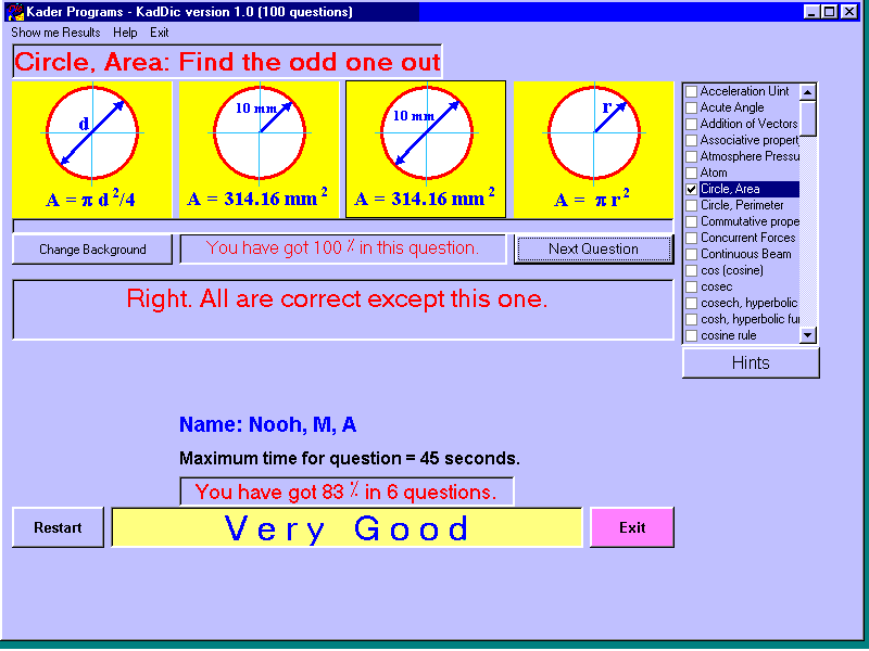
124The program tries to help you to test your basic engineering knowledge’s. In version 1.0, there are 100 questions about units, definitions, etc… The arrangement of the questions as will as the answers is random. In each question, there are four answers; one of them either wrong or doesn’t agree with the definition, try to find out this odd answer. If you do well from the first time your degree will be 100% in this question. If not your maximum degree will be reduced by 25% and so on. You will see the total degree for all previous questions.
The program tries to help you to test your basic engineering knowledge’s. In version 1.0, there are 100 questions about units, definitions, etc… The arrangement of the questions as will as the answers is random. In each question, there are four answers; one of them either wrong or doesn’t agree with the definition, try to find out this odd answer. If you do well from the first time your degree will be 100% in this question. If not your maximum degree will be reduced by 25% and so on. You will see the total degree for all previous questions.
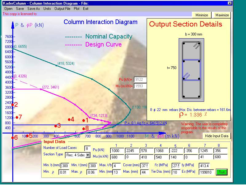
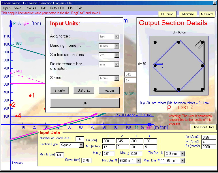
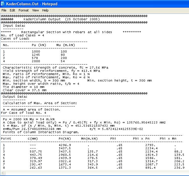
The program deals with tied short columns. It designs columns subjected to up to six cases of loading consisted of axial load and bending moment applied about the maximum principle axis. The program constructs the column strength interaction diagram (Bending moment-Axial load curve and check if all input cases of loading being within the design curve. If the input data of the cross-section is not sufficient the program increases them starting from the Min. Roh to the cross-sectional dimensions until all input cases of loading being within the design curve. The program suggests an arrangement of ties and draws them. (US and SI units)
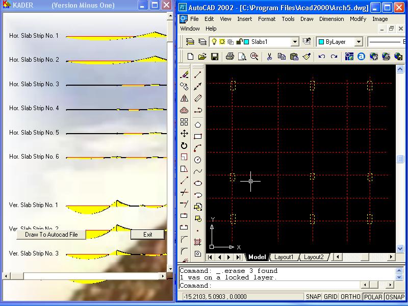
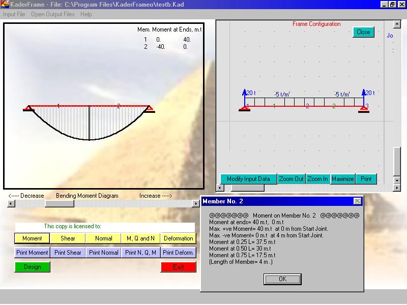
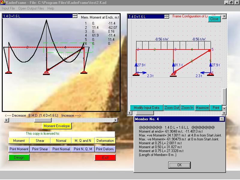
The program solves plane frames and continuous beams. It calculates the normal forces, shearing forces, and bending moments, draws and prints their diagrams. It also draws and prints the deformation shape. Text files of most calculated data are created on the same directory of the program. The program designs the sections byworking stress method and draw the frame and its sections to AutoCad 2000 file. The user can modify the design sections before and of course after drawing to AutoCad file. Only Metric system is used in this version.
The program tries to help you to test your basic engineering knowledge’s. In version 1.0, there are 100 questions about units, definitions, etc… The arrangement of the questions as will as the answers is random. In each question, there are four answers; one of them either wrong or doesn’t agree with the definition, try to find out this odd answer. If you do well from the first time your degree will be 100% in this question. If not your maximum degree will be reduced by 25% and so on. You will see the total degree for all previous questions.
The program tries to help you to test your basic engineering knowledge’s. In version 1.0, there are 100 questions about units, definitions, etc… The arrangement of the questions as will as the answers is random. In each question, there are four answers; one of them either wrong or doesn’t agree with the definition, try to find out this odd answer. If you do well from the first time your degree will be 100% in this question. If not your maximum degree will be reduced by 25% and so on. You will see the total degree for all previous questions.